
 107
107Measuring very small electrical signals can be difficult. Signals from sensors are tiny, and noise from other electronics can make them hard to read. An Instrumentation Amplifier (In-Amp) is a special type of amplifier that solves this problem. It is designed to amplify very small signals while blocking unwanted noise.
Let’s explore what instrumentation amplifiers are and how they work.

An instrumentation amplifier is a type of operational amplifier circuit that is specially designed to measure very small signals accurately. Think of it as a super-sensitive microphone for electrical signals. It picks up even the tiniest changes while ignoring background noise. It is widely used in measurement systems and sensor applications.
An instrumentation amplifier can:
Amplify tiny signals from sensors like strain gauges, thermocouples, and pressure transducers.
Reject common-mode noise, which is interference appearing equally on both input wires.
Provide high input impedance, so it does not load or disturb the sensor.
Give adjustable gain by changing just a single resistor.
Sensors, transducers, and bridge circuits often produce very small voltage signals, sometimes only a few millivolts. These signals are too weak for most electronic systems to read or process directly. For example, a strain gauge might produce a 50 mV change when weight is applied, and a thermocouple may generate just a few millivolts when the temperature changes. If we connect these sensors to a regular amplifier, the results may not be accurate.
The amplifier’s input might draw too much current from the sensor, which reduces the signal. Electrical noise from the environment can mix with the sensor signal, making it harder to read. In addition, standard amplifiers may not reject noise that appears on both input wires, called common-mode noise. Instrumentation amplifiers solve all these problems. They can amplify very small signals accurately while blocking unwanted noise, making them ideal for measuring sensor outputs reliably.
High Input Impedance: High input impedance means the amplifier does not draw significant current from the sensor. This prevents the sensor from being “loaded,” ensuring the signal remains intact.
High Gain: Instrumentation amplifiers can amplify very weak signals. Depending on the design, the gain can be set from 1 to several thousand.
High Common-Mode Rejection Ratio (CMRR): CMRR is the ability to reject common signals appearing on both input wires. For instance, electrical noise from a motor or AC supply often affects both wires equally. A high CMRR ensures that only the difference between inputs is amplified.
Low Output Impedance: Low output impedance ensures that the amplifier can drive other circuits without signal loss or distortion.
Single Resistor Gain Control: Unlike regular differential amplifiers, instrumentation amplifiers allow gain adjustment using a single resistor. This makes the design simpler and maintains accuracy.
Before we dive into instrumentation amplifiers, it’s helpful to understand the differential amplifier, also known as a subtractor.
A differential amplifier amplifies the difference between two input signals (V2 – V1). Its output voltage is proportional to this difference.
Problem With Basic Differential Amplifiers
A simple differential amplifier has some issues:
The input resistances may not be equal, causing inaccurate measurement.
Common-mode noise rejection may be limited.
Gain adjustment requires changing multiple resistors, which is cumbersome.
The solution is to add input buffers. A buffer is simply a unity-gain amplifier (voltage follower) that isolates the sensor from the main amplifier.
Adding buffers provides:
High input impedance at each input.
Better common-mode rejection, as both inputs are now symmetrical.
No loading effect on the sensor.
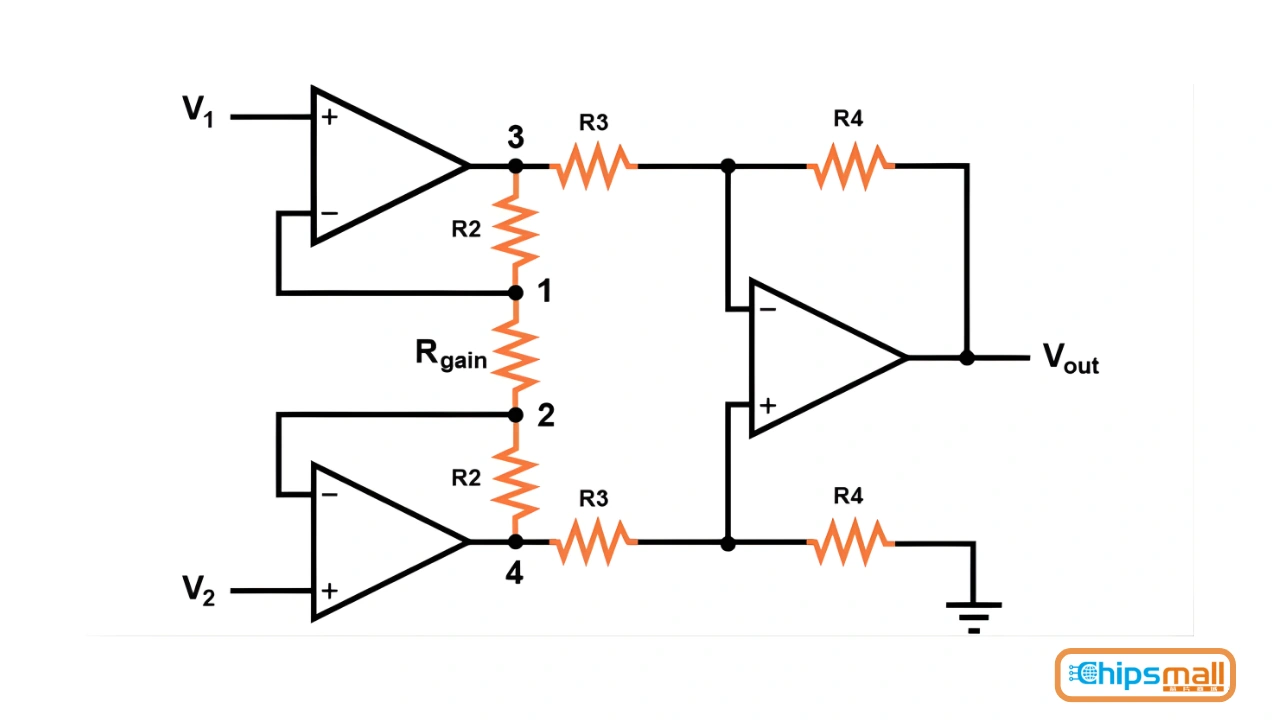
A typical instrumentation amplifier is made using three operational amplifiers (op-amps):
Two input buffer op-amps: Non-inverting amplifiers that receive signals V1 and V2 from the sensor. They provide high input impedance and isolate the sensor.
One differential amplifier op-amp: This op-amp amplifies the difference between the buffered inputs while rejecting common-mode noise.
The gain of an instrumentation amplifier is usually determined by a single resistor called RGR_GRG, connected between the two input buffers.
The formula for gain ADA_DAD is:
AD=1+2RRGA_D = 1 + \frac{2R}{R_G}AD=1+RG2R
Where:
RRR = feedback resistors on the input buffers
RGR_GRG = gain resistor
This allows simple gain adjustment without affecting the input impedance or CMRR.
Step 1: Buffer Stage: Each input signal (V1 and V2) goes through a non-inverting buffer. This ensures:
High input impedance
Matched signals for the next stage
Minimal effect of source impedance
Step 2: Gain Resistor: The outputs of the buffers are connected via resistor R_G. The voltage difference between V1 and V2 causes a current to flow through R_G, which sets the gain.
Step 3: Differential Amplifier: The third op-amp takes the outputs from the buffer stage and amplifies the difference. It ignores signals common to both inputs, effectively canceling noise.
Step 4: Output: The final output voltage is:
VOUT=AD⋅(V2−V1)V_{OUT} = A_D \cdot (V2 - V1)VOUT=AD⋅(V2−V1)
Where ADA_DAD is the overall differential gain.
Instrumentation amplifiers have many benefits compared to regular op-amps:
High Input Impedance: This means the amplifier does not draw current from the sensor, so the sensor signal stays strong and accurate without being weakened.
Easy Gain Adjustment: You can change the amplification by adjusting just one resistor, making it simple to set the desired signal strength without affecting other parts of the circuit.
High Common-Mode Rejection (CMRR): The amplifier can ignore unwanted noise or interference that appears on both input wires, such as electrical noise from motors or power lines. Only the actual difference between the input signals is amplified.
Symmetrical Design: The circuit is balanced, which ensures that measurements of the difference between two signals are very accurate.
Flexibility: Instrumentation amplifiers can work with many types of sensors, from strain gauges to thermocouples, making them suitable for a wide range of applications.
Noise Reduction: The built-in input buffers prevent noise from the sensor wires from affecting the amplified signal, giving a cleaner and more reliable output.
Instrumentation amplifiers are used wherever accurate measurement of small signals is important. Their ability to amplify weak signals while rejecting noise makes them essential in many fields.
Medical Devices: In medical equipment, instrumentation amplifiers are used to measure very small electrical signals from the human body. For example, an ECG (Electrocardiogram) uses an instrumentation amplifier to detect the tiny electrical signals generated by the heart. Similarly, an EEG (Electroencephalogram) measures brain waves, which are extremely weak signals, and instrumentation amplifiers make them strong enough to be recorded and analyzed. Blood pressure monitors also rely on these amplifiers to increase the small signals from pressure sensors, ensuring accurate readings for patients.
Industrial Controls: In industry, many sensors produce very small voltages that need to be amplified for monitoring and control. For instance, weighing scales use strain gauge bridges to measure weight, and the tiny signals from these sensors are amplified by instrumentation amplifiers. Temperature sensors, like RTDs (Resistance Temperature Detectors), generate small voltage changes that represent temperature variations; instrumentation amplifiers make these signals easier to read. Pressure sensors in industrial processes also produce low-level signals, which need amplification for accurate monitoring and control.
Data Acquisition: Instrumentation amplifiers are crucial in data acquisition systems, where they boost small voltages from sensors like strain gauges, thermocouples, and bridge networks. Without amplification, these tiny signals would be too weak to process. By increasing the signal strength while rejecting noise, instrumentation amplifiers allow computers and measurement devices to accurately record, analyze, and control processes.
Other Applications: Instrumentation amplifiers are also used in many other areas. In audio processing, they can amplify weak microphone signals while minimizing background noise. In sensor signal conditioning, they prepare signals from various sensors for further processing. They are also used in scientific experiments, where very small electrical changes need to be detected and measured accurately. Additionally, robotics and control systems often rely on instrumentation amplifiers to process signals from sensors and ensure precise control.
Designing an instrumentation amplifier involves selecting resistors and op-amps carefully. Let’s go through a simple example.
Example 1: Amplifying a Strain Gauge Signal: Suppose a strain gauge produces a signal from 0 to 50 mV. We want:
Differential amplifier gain (AV) = 2
Overall differential gain (AD) = 100
Step 1: Choose Feedback Resistors: The differential amplifier stage gain is:
AV=R2R1=2AV = \frac{R2}{R1} = 2AV=R1R2=2
If we choose R2=2kΩR2 = 2k\OmegaR2=2kΩ, then:
R1=R2AV=2kΩ2=1kΩR1 = \frac{R2}{AV} = \frac{2k\Omega}{2} = 1k\OmegaR1=AVR2=22kΩ=1kΩ
Step 2: Match Resistors for CMRR: To maintain common-mode rejection, we match all resistors:
R1=R3=1kΩR1 = R3 = 1k\OmegaR1=R3=1kΩ R2=R4=2kΩR2 = R4 = 2k\OmegaR2=R4=2kΩ
Step 3: Choose Buffer Resistors: Let’s choose R5=R6=5kΩR5 = R6 = 5k\OmegaR5=R6=5kΩ.
Step 4: Calculate Gain Resistor: Using the gain formula:
AD=1+2R5RGA_D = 1 + \frac{2R5}{R_G}AD=1+RG2R5 RG=2R5AD−1=2⋅5k100−1≈101ΩR_G = \frac{2R5}{A_D - 1} = \frac{2 \cdot 5k}{100 - 1} \approx 101 \OmegaRG=AD−12R5=100−12⋅5k≈101Ω
Step 5: Calculate Maximum Output: Maximum input = 50 mV, gain = 100:
VOUT(max)=AD⋅VIN(max)=100⋅0.05V=5VV_{OUT(max)} = AD \cdot V_{IN(max)} = 100 \cdot 0.05 V = 5VVOUT(max)=AD⋅VIN(max)=100⋅0.05V=5V
So the amplifier output ranges from 0 to 5 V. This example shows how simple it is to design a precise instrumentation amplifier.
While we can build instrumentation amplifiers from three separate op-amps, there are many integrated chips available, like:
AD524
AD620
INA105
INA115
INA332
These ICs combine all three op-amps into a single package, reducing circuit size, improving accuracy, and simplifying design.
High CMRR (often > 100 dB)
Adjustable gain via a single resistor
Low power consumption
Wide supply voltage range
Compact size for PCB design
The symbol for an instrumentation amplifier is like a regular op-amp, but with extra pins for:
RG (Gain Resistor)
VREF (Reference Voltage) VREF allows you to shift the output voltage to a desired reference, useful in single-supply systems.
To summarize, instrumentation amplifiers are better than regular op-amps in several ways:
High Accuracy: Perfect for sensitive measurements.
Simplified Gain Control: Only one resistor needs changing.
Noise Rejection: High CMRR removes unwanted interference.
Sensor Friendly: High input impedance protects sensors.
Stability: Symmetrical design prevents errors from resistor mismatch.
Here are some key formulas for designing and using instrumentation amplifiers:
Gain Formula: AD=1+2RRGA_D = 1 + \frac{2R}{R_G}AD=1+RG2R
Where RRR is the feedback resistor of the input buffers, RGR_GRG is the gain resistor.
Differential Output: VOUT=AD⋅(V2−V1)V_{OUT} = A_D \cdot (V2 - V1)VOUT=AD⋅(V2−V1)
Maximum Output Voltage: VOUT(max)=AD⋅VIN(max)V_{OUT(max)} = A_D \cdot V_{IN(max)}VOUT(max)=AD⋅VIN(max)
Calculating R_G: RG=2RAD−1R_G = \frac{2R}{A_D - 1}RG=AD−12R
Match Resistors: Even small mismatches can reduce CMRR.
Use Low-Noise Op-Amps: For very small signals, use precision, low-noise op-amps.
Keep Wires Short: Long sensor wires pick up more noise.
Use Shielding: Shielded cables reduce interference in industrial environments.
Use Proper Power Supply: Ensure op-amps receive clean, stable voltage.
Optional Trimming: A potentiometer can replace R_G for adjustable gain.
Instrumentation amplifiers are special circuits that amplify very small signals while blocking unwanted noise. With high input impedance, adjustable gain, and excellent noise rejection, they are perfect for measuring signals from sensors and transducers.
They are widely used in medical devices, industrial controls, data acquisition systems, and many other applications where accurate signal measurement is important.
So, if you want reliable and precise readings from weak signals, instrumentation amplifiers are the go-to solution in electronics.
Q1: What is an instrumentation amplifier used for?
Ans: An instrumentation amplifier is used to amplify very small signals from sensors while rejecting unwanted noise. It is commonly used in medical devices, industrial sensors, and data acquisition systems.
Q2: How is the gain of an instrumentation amplifier adjusted?
Ans: The gain can be adjusted by changing a single resistor called the gain resistor (RG). This makes it easy to set the amplification without affecting other parts of the circuit.
Q3: Why do instrumentation amplifiers have high input impedance?
Ans: High input impedance ensures that the amplifier does not draw current from the sensor, so the sensor signal stays accurate and is not weakened.
Q4: What does CMRR mean, and why is it important?
Ans: CMRR stands for Common-Mode Rejection Ratio. It measures the amplifier’s ability to ignore noise that appears equally on both input wires, so only the actual difference between the inputs is amplified.
Q5: Can instrumentation amplifiers be used with all types of sensors?
Ans: Yes, they are flexible and suitable for many sensors, including strain gauges, thermocouples, pressure sensors, and temperature sensors, making them ideal for precise measurements in various applications.
Disclaimer: The views and opinions expressed by individual authors or forum participants on this website do not represent the views and opinions of Chipsmall, nor do they represent Chipsmall's official policy.
A Complete Guide to Instrumentation Amplifiers for Accurate Sensor Measurements

share this blog to:
Chipsmall will provide you real-time product updates, limited-time deals.


Copyright © 2004-2026 Chipsmall.com All Rights Reserved.

Feedback
We appreciate your engagement with Chipsmall's products and services. Your opinion matters to us! Kindly take a moment to complete the form below. Your valuable feedback ensures that we consistently deliver the exceptional service you deserve. Thank you for being part of our journey towards excellence.

